Saturday, November 14, 2015

Thursday, November 12, 2015
HOW TO CALCULATE DEPTH OF SHALLOW FOUNDATION
Deciding the right depth of foundation for a building structure is an important step in the process of building design. Information given in this post will help you decide the proper depth of foundation for a building.
After reading this post you will be able to answer the following questions.
What is a foundation?
What are the factors affecting depth of foundation?
How to calculate depth of foundation?
What are the factors affecting depth of foundation?
How to calculate depth of foundation?
I- WHAT IS FOUNDATION
Foundation is that part of the structure which receives load of the superstructure and then transmits that load to soil underneath in such a manner so that the soil never fails in shear or never goes through excessive settlement of differential settlement.
II- FACTORS AFFECTING DEPTH OF FOUNDATION:
Before calculating depth of shallow foundation, the following factors have to be considered well in advance.
1. Foundation should be placed at such a depth so that it is safe against damages due to swelling, shrinkage or freezing of sub soil.
2. Bearing capacity of soil beneath the foundation must be adequate to support the load coming from foundation.
3. If foundation has to be placed on cohesive soil then the settlement due to consolidation should not be excessive.
4. Never place foundation on loose or disturbed soils which have a tendency to erode by wind or flood.
5. If possible then foundation should be placed above ground water table as this can avoid cost of pumping, and can prevent instability of soil due to seepage of water into the bottom of an excavation.
6. Make an investigation on foundation soil to know its physical and chemical properties, because presence of sulphate can damage foundation.
III- CALCULATION OF DEPTH OF FOUNDATION
The minimum depth of shallow foundation for a soil can be calculated using the following formula as suggested by Rankine. This is called Rankine’s Formula.
Dmin = (q/g) * [(1 – sinØ) / (1 + sinØ)]2
Where,
Dmin = Minimum depth of foundation in m
g = Density of unit weight of soil in kN/m3
Ø = Angle of repose in Degrees
q = Intensity of load or Safe bearing capacity of soil in kN/m2
Example Calculation
Example Calculation
IV- EXAMPLE:
Calculate the minimum depth required for a foundation to transmit a pressure 55 kN/m2 in a cohesionless soil having density 16 kN/m3 and angle of repose 200?
GIVEN DATA:
Intensity of pressure (q) = 55 kN/m2
Density of soil (g) = 16 kN/m3
Angle of repose (Ø) = 200
CALCULATION:
Minimum depth of foundation, according to Rankine,
Dmin = (q/g) * [(1 – sinØ) / (1 + sinØ)]2
Dmin = (55/16) * [(1 – sin200) / (1 + sin200)]2
Dmin = 0.82 m
V- HELPFUL POINTS
For preliminary calculation of depth of foundation, the values of density and angle of repose, as given in the following table can be used.
Soil Type Angle of Repose (in Degree) Unit weight (in kN/m3)
Dry sand 25 – 35 16.0
Moist sand 30 – 35 18.4
Wet sand 15 – 25 19.2
Dry & compacted sand 35 19.2
Clean gravel 30 – 40 17.9
Mixture of gravel & sand 25 – 40 19.2
Rubble stone 45 19.2
Dry clay 30 17.6
Wet clay 15 19.2
Ash 40 6.4
Soil Type Angle of Repose (in Degree) Unit weight (in kN/m3)
Dry sand 25 – 35 16.0
Moist sand 30 – 35 18.4
Wet sand 15 – 25 19.2
Dry & compacted sand 35 19.2
Clean gravel 30 – 40 17.9
Mixture of gravel & sand 25 – 40 19.2
Rubble stone 45 19.2
Dry clay 30 17.6
Wet clay 15 19.2
Ash 40 6.4
NOTE:
1) The values given the table above are approximate value.
2) To know the density of soil on site you have to test it onsite. There are two common methods which are widely used for determination of density of soil on site. Click the following two links to read the test procedure.
2) To know the density of soil on site you have to test it onsite. There are two common methods which are widely used for determination of density of soil on site. Click the following two links to read the test procedure.
Wednesday, October 28, 2015
REPAIR OF SMALL AND LARGE CRACKS IN CONCRETE
Repair of small and medium cracks in concrete:
Small and medium cracks in reinforced concrete and masonry structures reduce their strength considerably to bear the design loads. Thus repair of such cracks is necessary to restore the designed strength of members.
The repair of small and medium cracks is done by first marking out the critical damaged zones in concrete members. Then these cracks can be repaired by injecting cement grout or chemical grouts or by providing jacketing. The smaller cracks less than 0.75 mm width can be effectively repair by using pressure injection of epoxy.
The surface of the member near cracks is thoroughly cleaned. Loose materials are removed and plastic injection ports are placed along the length of crack at an interval equal to the thickness of the structural member. These ports are placed on both sides of the member and secured in placed with the help of epoxy seal.
When the epoxy seal has hardened, the low viscosity resin is injected into one port at a time starting from the port at lowest level and moving upwards. The injection through port is continued till the resin flows out from the adjacent port or from the other side of the member. Then the current injection port is closed and epoxy injection is continued from the adjacent port.

This process is carried out in sequence till all the ports and cracks are filled with the grout. This method can be used for all types of structural members such are beams, columns, walls and slabs. This method can also to repair of small cracks in individual masonry blocks or for filling large continuous cracks.
Repair of Large Cracks and Crushed Concrete:
Repair of large cracks (cracks wider than 5mm) and crushed concrete and masonry structure cannot be done using pressure injection or grouting. For repair of large cracks and crushed concrete, following procedure can be adopted:
1. The surface of cracks or crushed concrete is cleaned and all the loose materials are removed. These are then filled with quick setting cement mortar grouts.
2. If the cracks are large, then these cracks are dressed to have a V groove at both sides of the member for easy placement of grouts.

Fig: Filling of cement mortar and stone chips in large cracks in masonry walls.
3. For cracks which are very large, filler materials such as stone chips can be used.
4. Additional reinforcement and shear reinforcements can be used for heavily damaged concrete members or wherever necessary based on requirements.
These additional reinforcement should be protected from corrosion by using polymer mortar or epoxy coatings.
5. For damaged walls and roofs, additional reinforcement in the form of mesh is used on one side or both sides of the members. These mesh should sufficiently tied with existing members.
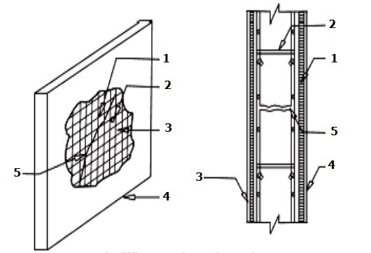
Fig: Reinforcement meshes in repair of roof slabs and walls. 1. Wire mesh on front face, 2. Clamps, 3. Wire mesh on back face, 4. Cement plaster, 5. Crack in member.
6. Stitching of cracks are done to prevent the widening of the existing cracks. In this case, holes of 6 to 10mm are drilled on both sides of the crack. Then these drilled holes are cleaned, legs of stitching dogs are anchored with short legs. The stitching of cracks is not a method of crack repair or to gain the lost strength, this method is used to prevent the cracks from propagating and widening.
Saturday, October 24, 2015
Monday, October 19, 2015

Friday, October 9, 2015

Tuesday, October 6, 2015
REALFLOW 2012 FREE DOWNLOAD

RealFlow is a fluid and dynamics simulation tool for the 3D and visual effects industry, developed by Next Limit Technologies in Madrid, Spain. This stand-alone application can be used in conjunction with other 3D programs to simulate fluids, water surfaces, fluid-solid interactions, rigid bodies, soft bodies and meshes. In 2008, the Next Limit Technologies was awarded a Technical Achievement Award by the Academy of Motion Picture Arts and Sciences for their development of the RealFlow software and its contribution to the production of motion pictures. In 2015, Next Limit Technologies announced the upcoming release of RealFlow Core for Cinema 4D.

Sunday, October 4, 2015
HOW TO WRITE MSc THESIS
Editorial
- Font: Times New Roman, 12 Size
- Line Spacing: Double
- Borders: 1 in, all four sides
- First Level Heading: 12, Bold, Capital
- Second Level Heading: 12, Bold, First letter of every word Capital
- Third Level Heading: 12, Regular, Italic, First letter of every word Capital
- No Empty spaces below Figures and Tables
- Every Figure and Table must have caption
Sequence
- Abstract
- Dedication (optional)
- Acknowledgements (optional)
- Table of Content
- List of Figures
- List of Tables
Chapter 1: Introduction
1.1 Problem Statement
1.2 Objectives of Research
1.3 Research Methodology
1.4 Organization of Thesis
Chapter 2: Literature Review
Chapter 3: Experimental Work
Chapter 4: Analytical Work
Chapter 5: Results and Discussion
Chapter 6: Conclusions and Recommendation
References
1 Page Resume
1.1 Problem Statement
1.2 Objectives of Research
1.3 Research Methodology
1.4 Organization of Thesis
Chapter 2: Literature Review
Chapter 3: Experimental Work
Chapter 4: Analytical Work
Chapter 5: Results and Discussion
Chapter 6: Conclusions and Recommendation
References
1 Page Resume
Abstract:
It should be limited to 250-300 words. Discuss the rationale behind the study, general approach to the problem, pertinent results, and important conclusions or new questions. Write abstract after the rest of the thesis has been completed.
It should be limited to 250-300 words. Discuss the rationale behind the study, general approach to the problem, pertinent results, and important conclusions or new questions. Write abstract after the rest of the thesis has been completed.
Literature Review
When you write about historical context in terms of who has done what, use first person active voice and refer to the author’s last name. Do not jump from one topic to the other. Connect statements from various authors so that everything is in flow. If you copy something directly from a paper without putting it in your own words, put it quotation marks.
When you write about historical context in terms of who has done what, use first person active voice and refer to the author’s last name. Do not jump from one topic to the other. Connect statements from various authors so that everything is in flow. If you copy something directly from a paper without putting it in your own words, put it quotation marks.
Experimental Work/Methodology…… (HOW?)
Use past tense except when referring to established facts. Most authors use third person passive voice. Omit all explanatory information and background. Save it for the discussion.
Use past tense except when referring to established facts. Most authors use third person passive voice. Omit all explanatory information and background. Save it for the discussion.
Results…… (WHAT?)
Make this section a completely objective report of the results, and save all interpretation for the discussion. Use figures and tables and refer each of them in text. In text, describe each of your results, pointing the reader to observations that are most relevant. Provide a context, such as by describing the question that was addressed by making a particular observation. Also describe results of experiments that are not presented in figures or tables.
Make this section a completely objective report of the results, and save all interpretation for the discussion. Use figures and tables and refer each of them in text. In text, describe each of your results, pointing the reader to observations that are most relevant. Provide a context, such as by describing the question that was addressed by making a particular observation. Also describe results of experiments that are not presented in figures or tables.
Discussion….. (WHY?)
Here we write Interpretation of results and support for all the conclusions, using evidence from experiment. When you explain a phenomenon you must describe mechanisms that may account for the observation. If results differ from expectations, explain why that may have happened. If results agree, then describe the theory that the evidence supported. Decide if the experimental design adequately addressed the hypothesis. Try to offer alternative explanations if reasonable alternatives exist. Do not present superficial interpretation that more or less re-states the results. It is necessary to suggest why results came out as they did, focusing on the mechanisms behind the observations.
Here we write Interpretation of results and support for all the conclusions, using evidence from experiment. When you explain a phenomenon you must describe mechanisms that may account for the observation. If results differ from expectations, explain why that may have happened. If results agree, then describe the theory that the evidence supported. Decide if the experimental design adequately addressed the hypothesis. Try to offer alternative explanations if reasonable alternatives exist. Do not present superficial interpretation that more or less re-states the results. It is necessary to suggest why results came out as they did, focusing on the mechanisms behind the observations.
Don’ts
- Do not be subjective: “We felt that……”
- Avoid superlative such as “huge,” “incredible,” “wonderful,” “exciting, “etc.
- Talk in terms of numbers and percentages.
Conclusions
- What can you say about the work that you couldn’t before?
- What are the broader implications of the work?
- Write conclusions with FRESH MIND,
Proofreading
- Take a break before proofreading. The goal is to return with a fresh eyes and mind
- Leave yourself enough time. No speeding
- Get others involved
- Read your thesis out loud
- Print out a copy to proofread
Sample References
- Banthia, N., Al-Asaly, M., and Ma, S., “Behavior of Concrete Slabs Reinforced with Fiber-Reinforced Plastic Grid,” Journal of Materials in Civil Engineering, V. 7, No. 4, 1995, pp. 252-257.
- Ghannoum, C. M., “Effect of High-Strength Concrete on the Performance of Slab-Column Specimens,” MEngrg. Thesis, Department of Civil Engineering and Applied Mechanics, McGill University, Montreal, QC, Canada, 1998, 91 pp.
- ACI Committee 318, “Building Code Requirements for Structural Concrete (ACI 318-08) and Commentary,” American Concrete Institute, Farmington Hills, MI, 2008, 473 pp.
- British Standard Institution, “Structural Use of Concrete,” Standard BS 8110, London, UK,1997, 168 pp.
- Mirmiran, A., “Length Effects on FRP-Reinforced Concrete Columns,” Proceedings of the 2nd International Conference on Composites in Infrastructure, Tucson, AZ, 1998, pp. 518-532.
Complied by:
Dr. M. Azhar Saleem
Director, Bridge Engineering Lab,
Department of Civil Engineering
UET Lahore
Dr. M. Azhar Saleem
Director, Bridge Engineering Lab,
Department of Civil Engineering
UET Lahore

Thursday, October 1, 2015

PROFESSIONAL CONSTRUCTION ENGINEERING CALCULATOR

This is a structural engineering calculator, which was only used in the building. The engineering calculator helps you to calculate the size of your building. This software converts all your units and is not bothered about the fall. With this software you are able to roof area, stairs and get all the units of the metric system.

Tuesday, September 29, 2015


Monday, September 28, 2015

TRUSS4 ROOF TRUSS SOFTWARE
Software suite TRUSS4 is intended for analysis of timber truss structures connected with punched metal plate fasteners. TRUSS4 offers complete process of a project from truss style and quotation to producing documentation and mechanically generated outputs for machinery instrumentality.

Size:- 842 kb


Sunday, September 27, 2015


Saturday, September 26, 2015
GRASP FREE DOWNLOAD
Major features include:
- Modeling and analysis of multiple models in one file
- Presetting of default load cases and load factors
- Internal and automatic tracking of node numbers and member incidences
- Display the structural model at all times on the screen during analysis and superimposition of the analysis results on the model after analysis
- A Structure wizard provides a step-by-step guideline for the generation of a multistorey structural models
- Supports SI, US and metric units and use of mixed units
- Apply loads on nodes and on members in multiple load cases.
- View and print analysis results for the full structure up to 20 sections for a member
- Diagram with value and tables
- Special spring and inclined supports
Friday, September 25, 2015

Thursday, September 24, 2015


BASICS OF A BRIDGE

Because of the wide range of structural possibilities, this article shows only the most common fixed (non-movable) bridge types. The drawings are not to scale. Additional related info is found on the other Terminology pages which are linked to the left.
The four main factors are used in describing a bridge. By combining these terms one may give a general description of most bridge types.
- Span (simple, continuous, cantilever), material (stone, concrete, metal, etc.)
- Placement of the travel surface in relation to the structure (deck, pony, through)
- Form (beam, arch, truss, etc.).
1. Span
The three basic types of spans are shown below. Any of these spans may be constructed using beams, girders or trusses. Arch bridges are either simple or continuous (hinged). A cantilever bridge may also include a suspended span.
2. Travel Surface
Examples of the three common travel surface configurations are shown in the Truss type drawings below. In aDeck configuration, traffic travels on top of the main structure; in a Pony configuration, traffic travels between parallel superstructures which are not cross-braced at the top; in a Through configuration, traffic travels through the superstructure (usually a truss) which is cross-braced above and below the traffic.

3. Form
Beam & Girder Types
Simple deck beam bridges are usually metal or reinforced concrete. Other beam and girder types are constructed of metal. The end section of the two deck configuration shows the cross-bracing commonly used between beams. The pony end section shows knee braces which prevent deflection where the girders and deck meet.

One method of increasing a girder's load capacity while minimizing its web depth is to add haunches at the supported ends. Usually the center section is a standard shape with parallel flanges; curved or angled flanged ends are riveted or bolted using splice plates. Because of the restrictions incurred in transporting large beams to the construction site, shorter, more manageable lengths are often joined on-site using splice plates.

Many modern bridges use new designs developed using computer stress analysis. The rigid frame type has superstructure and substructure which are integrated. Commonly, the legs or the intersection of the leg and deck are a single piece which is riveted to other sections.

Orthotropic beams are modular shapes which resist stress in multiple directions at once. They vary in cross-section and may be open or closed shapes.

Arch Types
There are several ways to classify arch bridges. The placement of the deck in relation to the superstructure provides the descriptive terms used in all bridges: deck, pony, and through.
Also the type of connections used at the supports and the midpoint of the arch may be used - - counting the number of hinges which allow the structure to respond to varying stresses and loads. A through arch is shown, but this applies to all type of arch bridges.


Another method of classification is found in the configuration of the arch. Examples of solid-ribbed, brace-ribbed(trussed arch) and spandrel-braced arches are shown. A solid-ribbed arch is commonly constructed using curved girder sections. A brace-ribbed arch has a curved through truss rising above the deck. A spandrel-braced arch or open spandrel deck arch carries the deck on top of the arch.

Some metal bridges which appear to be open spandrel deck arch are, in fact, cantilever; these rely on diagonal bracing. A true arch bridge relies on vertical members to transmit the load which is carried by the arch.

The tied arch (bowstring) type is commonly used for suspension bridges; the arch may be trussed or solid. The trusses which comprise the arch will vary in configuration, but commonly use Pratt or Warren webbing. While a typical arch bridge passes its load to bearings at its abutment; a tied arch resists spreading (drift) at its bearings by using the deck as a tie piece.

Masonry bridges, constructed in stone and concrete, may have open or closed spandrels A closed spandrel is usually filled with rubble and faced with dressed stone or concrete. Occasionally, reinforced concrete is used in building pony arch types

Truss - Simple Types
A truss is a structure made of many smaller parts. Once constructed of wooden timbers, and later including iron tension members, most truss bridges are built of metal. Types of truss bridges are also identified by the terms deck, pony and through which describe the placement of the travel surface in relation to the superstructure (see drawings above). The king post truss is the simplest type; the queen post truss adds a horizontal top chord to achieve a longer span, but the center panel tends to be less rigid due to its lack of diagonal bracing.


Wednesday, September 23, 2015

Subscribe to:
Posts (Atom)