Sunday, May 15, 2016

Saturday, November 14, 2015

Thursday, November 12, 2015
HOW TO CALCULATE DEPTH OF SHALLOW FOUNDATION
Deciding the right depth of foundation for a building structure is an important step in the process of building design. Information given in this post will help you decide the proper depth of foundation for a building.
After reading this post you will be able to answer the following questions.
What is a foundation?
What are the factors affecting depth of foundation?
How to calculate depth of foundation?
What are the factors affecting depth of foundation?
How to calculate depth of foundation?
I- WHAT IS FOUNDATION
Foundation is that part of the structure which receives load of the superstructure and then transmits that load to soil underneath in such a manner so that the soil never fails in shear or never goes through excessive settlement of differential settlement.
II- FACTORS AFFECTING DEPTH OF FOUNDATION:
Before calculating depth of shallow foundation, the following factors have to be considered well in advance.
1. Foundation should be placed at such a depth so that it is safe against damages due to swelling, shrinkage or freezing of sub soil.
2. Bearing capacity of soil beneath the foundation must be adequate to support the load coming from foundation.
3. If foundation has to be placed on cohesive soil then the settlement due to consolidation should not be excessive.
4. Never place foundation on loose or disturbed soils which have a tendency to erode by wind or flood.
5. If possible then foundation should be placed above ground water table as this can avoid cost of pumping, and can prevent instability of soil due to seepage of water into the bottom of an excavation.
6. Make an investigation on foundation soil to know its physical and chemical properties, because presence of sulphate can damage foundation.
III- CALCULATION OF DEPTH OF FOUNDATION
The minimum depth of shallow foundation for a soil can be calculated using the following formula as suggested by Rankine. This is called Rankine’s Formula.
Dmin = (q/g) * [(1 – sinØ) / (1 + sinØ)]2
Where,
Dmin = Minimum depth of foundation in m
g = Density of unit weight of soil in kN/m3
Ø = Angle of repose in Degrees
q = Intensity of load or Safe bearing capacity of soil in kN/m2
Example Calculation
Example Calculation
IV- EXAMPLE:
Calculate the minimum depth required for a foundation to transmit a pressure 55 kN/m2 in a cohesionless soil having density 16 kN/m3 and angle of repose 200?
GIVEN DATA:
Intensity of pressure (q) = 55 kN/m2
Density of soil (g) = 16 kN/m3
Angle of repose (Ø) = 200
CALCULATION:
Minimum depth of foundation, according to Rankine,
Dmin = (q/g) * [(1 – sinØ) / (1 + sinØ)]2
Dmin = (55/16) * [(1 – sin200) / (1 + sin200)]2
Dmin = 0.82 m
V- HELPFUL POINTS
For preliminary calculation of depth of foundation, the values of density and angle of repose, as given in the following table can be used.
Soil Type Angle of Repose (in Degree) Unit weight (in kN/m3)
Dry sand 25 – 35 16.0
Moist sand 30 – 35 18.4
Wet sand 15 – 25 19.2
Dry & compacted sand 35 19.2
Clean gravel 30 – 40 17.9
Mixture of gravel & sand 25 – 40 19.2
Rubble stone 45 19.2
Dry clay 30 17.6
Wet clay 15 19.2
Ash 40 6.4
Soil Type Angle of Repose (in Degree) Unit weight (in kN/m3)
Dry sand 25 – 35 16.0
Moist sand 30 – 35 18.4
Wet sand 15 – 25 19.2
Dry & compacted sand 35 19.2
Clean gravel 30 – 40 17.9
Mixture of gravel & sand 25 – 40 19.2
Rubble stone 45 19.2
Dry clay 30 17.6
Wet clay 15 19.2
Ash 40 6.4
NOTE:
1) The values given the table above are approximate value.
2) To know the density of soil on site you have to test it onsite. There are two common methods which are widely used for determination of density of soil on site. Click the following two links to read the test procedure.
2) To know the density of soil on site you have to test it onsite. There are two common methods which are widely used for determination of density of soil on site. Click the following two links to read the test procedure.
Wednesday, October 28, 2015
REPAIR OF SMALL AND LARGE CRACKS IN CONCRETE
Repair of small and medium cracks in concrete:
Small and medium cracks in reinforced concrete and masonry structures reduce their strength considerably to bear the design loads. Thus repair of such cracks is necessary to restore the designed strength of members.
The repair of small and medium cracks is done by first marking out the critical damaged zones in concrete members. Then these cracks can be repaired by injecting cement grout or chemical grouts or by providing jacketing. The smaller cracks less than 0.75 mm width can be effectively repair by using pressure injection of epoxy.
The surface of the member near cracks is thoroughly cleaned. Loose materials are removed and plastic injection ports are placed along the length of crack at an interval equal to the thickness of the structural member. These ports are placed on both sides of the member and secured in placed with the help of epoxy seal.
When the epoxy seal has hardened, the low viscosity resin is injected into one port at a time starting from the port at lowest level and moving upwards. The injection through port is continued till the resin flows out from the adjacent port or from the other side of the member. Then the current injection port is closed and epoxy injection is continued from the adjacent port.

This process is carried out in sequence till all the ports and cracks are filled with the grout. This method can be used for all types of structural members such are beams, columns, walls and slabs. This method can also to repair of small cracks in individual masonry blocks or for filling large continuous cracks.
Repair of Large Cracks and Crushed Concrete:
Repair of large cracks (cracks wider than 5mm) and crushed concrete and masonry structure cannot be done using pressure injection or grouting. For repair of large cracks and crushed concrete, following procedure can be adopted:
1. The surface of cracks or crushed concrete is cleaned and all the loose materials are removed. These are then filled with quick setting cement mortar grouts.
2. If the cracks are large, then these cracks are dressed to have a V groove at both sides of the member for easy placement of grouts.

Fig: Filling of cement mortar and stone chips in large cracks in masonry walls.
3. For cracks which are very large, filler materials such as stone chips can be used.
4. Additional reinforcement and shear reinforcements can be used for heavily damaged concrete members or wherever necessary based on requirements.
These additional reinforcement should be protected from corrosion by using polymer mortar or epoxy coatings.
5. For damaged walls and roofs, additional reinforcement in the form of mesh is used on one side or both sides of the members. These mesh should sufficiently tied with existing members.
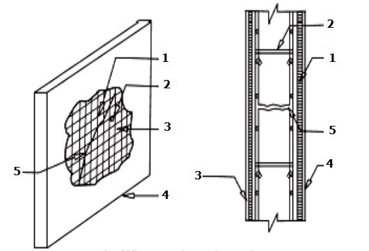
Fig: Reinforcement meshes in repair of roof slabs and walls. 1. Wire mesh on front face, 2. Clamps, 3. Wire mesh on back face, 4. Cement plaster, 5. Crack in member.
6. Stitching of cracks are done to prevent the widening of the existing cracks. In this case, holes of 6 to 10mm are drilled on both sides of the crack. Then these drilled holes are cleaned, legs of stitching dogs are anchored with short legs. The stitching of cracks is not a method of crack repair or to gain the lost strength, this method is used to prevent the cracks from propagating and widening.
Saturday, October 24, 2015
Subscribe to:
Comments (Atom)